How to Optimize Winding Turns for an Iron-Based Nanocrystalline Ring Core

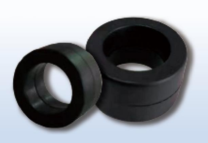
Winding turns play an important role in the performance of an iron-based nanocrystalline ring core for common mode inductance. The number of turns affects inductance, impedance, winding resistance, and the overall design of a common mode choke. Choosing the right winding configuration can help engineers achieve effective electromagnetic interference suppression without making the component unnecessarily large or difficult to manufacture.
However, adding more turns does not always produce a better result. Excessive winding can increase copper resistance and parasitic capacitance, while too few turns may not provide the required impedance in the target frequency range.
For manufacturers of EMI filters, power supplies, and industrial electrical equipment, understanding how to optimize winding turns is essential when designing a reliable common mode inductor. This guide explains the main factors engineers should consider and how Hall Magnetics can support magnetic core selection for different applications.
Define the Target Inductance and Impedance
The first step is to establish the electrical performance required from the common mode choke. Engineers should identify the target common mode impedance, the frequency range where noise suppression is needed, and the expected operating conditions.
Inductance is an important design parameter, but it should not be the only selection criterion. In EMI filtering applications, a core and winding combination must provide suitable impedance across the frequencies where unwanted common mode noise occurs.
For an initial estimate, the inductance of a winding on a magnetic core can often be approximated by:
L ≈ AL × N²
Here, L represents inductance, AL is the core inductance factor under specified measurement conditions, and N is the number of turns. This relationship is useful for preliminary calculations, but actual performance should be verified under the relevant frequency and operating conditions.
When selecting an iron-based nanocrystalline ring core for common mode inductance, engineers should use the core’s specified AL value and confirm the measurement frequency and test conditions. The final design should be validated by measuring the impedance curve rather than relying only on a calculated inductance value.
Consider the Advantages of Iron-Based Nanocrystalline Material
Iron-based nanocrystalline cores are used in common mode chokes and EMI filters because their magnetic properties can support high inductance and effective noise suppression in suitable designs.
Their high permeability can help engineers achieve a target inductance with fewer winding turns than may be required with some alternative core materials. Fewer turns can reduce copper usage and help limit winding resistance, although the actual result depends on the core dimensions, wire size, and electrical requirements.
For a nanocrystalline ring core for common mode choke design, material selection should be based on the required impedance over the target frequency range, not simply on the highest available permeability.
Engineers should also consider core loss, operating temperature, current conditions, and the available winding space. Selecting the appropriate core provides a better starting point for optimizing the number of turns.
Balance Winding Turns with Wire Resistance
Every additional turn requires more wire. As the winding length increases, the DC resistance of the coil may also increase, depending on the wire diameter and winding arrangement.
Higher winding resistance can contribute to power loss and temperature rise. This is particularly important in power supplies and industrial equipment where the common mode choke must carry continuous operating current.
When optimizing winding turns for an iron-based nanocrystalline ring core, engineers should consider both the required magnetic performance and the electrical resistance of the winding.
Using a suitable wire diameter can help control resistance, but thicker wire requires more winding space and may limit the number of turns that fit on the core. The best design balances wire size, turn count, current requirements, and the available core window.
A practical design process compares several winding configurations and measures their electrical performance and temperature rise under representative operating conditions.
Account for Parasitic Capacitance and Frequency Response
More winding turns can increase the parasitic capacitance between adjacent wires and winding sections. This capacitance can affect the frequency response of the finished common mode choke, especially when noise suppression is required over a broad frequency range.
Consequently, a winding with a higher measured inductance does not necessarily provide better EMI suppression at every frequency. The actual impedance depends on the core material, winding arrangement, parasitic elements, and operating frequency.
For iron-based nanocrystalline cores used in EMI filters, engineers should evaluate the impedance-versus-frequency curve of the completed component. The design should provide sufficient impedance in the target noise band while avoiding unwanted performance reductions caused by parasitic effects.
Winding layout, spacing, and the arrangement of the two windings should be considered together. Testing the finished component is the most reliable way to confirm that the selected number of turns meets the application requirements.
Maintain Correct Winding Configuration in Common Mode Chokes
A common mode choke normally uses two windings on a shared magnetic core. These windings are arranged so that the magnetic flux produced by normal differential-mode current largely cancels, while the flux produced by common-mode noise adds.
This configuration allows the choke to impede common-mode noise while permitting normal load current to pass with relatively low impedance.
When optimizing the winding turns of a nanocrystalline common mode choke core, engineers must consider not only the number of turns but also winding polarity, direction, and symmetry. Incorrect winding connections can change the intended magnetic behavior and reduce filtering effectiveness.
The two windings should follow the specified electrical design, with suitable attention to conductor size, insulation, spacing, and terminal configuration. The completed choke should be checked for correct connections and tested in the intended circuit.
Check Core Dimensions and Available Winding Space
The core’s inner diameter, outer diameter, height, and cross-sectional dimensions determine how much space is available for winding. A design that requires too many turns may be difficult to manufacture on a small ring core.
Insufficient winding space can lead to crowded wire placement, difficult assembly, or compromised insulation spacing. These issues may affect production consistency and the suitability of the finished component for its operating environment.
Before finalizing the number of turns, engineers should verify the available winding area, wire diameter, insulation requirements, and manufacturing tolerances.
For a custom iron-based nanocrystalline ring core, discussing the target winding configuration and mechanical constraints with the supplier early in the design process can help avoid costly revisions later.
Test and Refine the Winding Design
Calculations provide a starting point, but testing is necessary to determine whether the selected winding turns deliver the expected performance.
A practical validation process may include:
- Measuring inductance under specified test conditions
- Measuring impedance across the target frequency range
- Checking winding resistance
- Evaluating temperature rise at representative current levels
- Verifying winding polarity and electrical connections
- Testing EMI suppression in the intended circuit
Engineers should also consider differences between prototype and mass-production conditions. Changes in wire placement, winding tension, assembly methods, or core characteristics may affect the results.
Documenting the tested winding configuration and acceptance criteria helps maintain consistent performance across production batches.
Work with a Magnetic Core Supplier Early
Choosing a core only after the winding design has been finalized can limit the available options. Coordinating core selection and winding requirements early can help engineers evaluate the complete component more efficiently.
Hall Magnetics provides magnetic core solutions for electrical and power electronics applications. When evaluating an iron-based nanocrystalline ring iron core for common mode inductance from Hall Magnetics, customers can discuss core dimensions, magnetic characteristics, target impedance, operating frequency, and application requirements.
Providing these details helps clarify whether a proposed core is suitable for the intended design. Final winding turns should still be determined through engineering calculations and prototype validation, rather than assuming that one turn count will work for every application.
Conclusion
Optimizing winding turns for an iron-based nanocrystalline ring core requires balancing inductance, impedance, winding resistance, parasitic capacitance, current requirements, and available space. Increasing the number of turns may improve inductance, but it can also increase resistance and parasitic effects that influence the finished component’s performance.
The most effective approach is to define the target noise frequency range, select a suitable core, calculate an initial winding configuration, and verify the results through electrical and thermal testing.
Hall Magnetics can support customers in evaluating magnetic core options for common mode inductors and EMI filter applications. By combining clear electrical requirements with suitable core selection and systematic testing, engineers can develop winding designs that better meet their performance and manufacturing needs.
FAQ
1. How do winding turns affect an iron-based nanocrystalline ring core?
Winding turns affect inductance and can influence impedance, winding resistance, parasitic capacitance, and temperature rise. The final result depends on the core characteristics, wire size, winding arrangement, and operating frequency.
2. Do more winding turns always improve common mode choke performance?
No. More turns may increase inductance, but they can also increase winding resistance and parasitic capacitance. The optimum number depends on the required impedance across the target frequency range and the component’s electrical and thermal limits.
3. How can I determine the correct number of turns for a nanocrystalline common mode choke?
Start with the required impedance, operating frequency, core AL value, current requirements, and available winding space. Use these parameters for preliminary calculations, then validate the finished component through inductance, impedance, resistance, temperature-rise, and application testing.